CVT- Continuously Variable Transmission

Waveform Gearing
Or
"How to make a chain go faster than its sprocket."

Power generating mechanisms work most efficiently when they operate within a relatively narrow range of speeds, while specific power applications might require a broader range of speeds, e.g., electric drill, motorcycle, lathe, chain saw. Drive gearing is used to bridge this gap, ensuring the power is delivered efficiently but at the right speeds for the application.

Traditional Gearing
Traditional gearing does this by using various diameters of toothed sprockets or gears to achieve the required ratio. Gear changing devices then engage additional gears or reconnect a chain. Whilst well proven and familiar the disadvantages of this approach are often overlooked. Continuous gearing changing is not possible. A clutch or torque converter is often required to disconnect the drive between gear changes. Adding gears consumes more space or when using chain drives, increases misalignment. Overall the number of parts involved can be considerable and the cost high, especially when adding features such as automatic gearing.

Waveform Gearing
Waveform Gearing provides a solution to some of these gearing problems by providing a simple, low cost, continuously variable gearing with the option of automatic gearing.


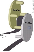
How Waveform Gearing Works

 Waveform gearing simply generates a wave in the path of a chain (or belt) transmission to increase its gearing.
 Refer drawing: The Input Drive engages the Idler Sprocket causing it to rotate counter clockwise. The meshing of these two sprockets is utilised to pull the chain between them following the waveform path of the sprocket teeth.
This in turn will cause the Final Drive Sprocket to rotate. The extent of tooth meshing of Drive Sprocket with Idler Sprocket determines the waveform amplitude (see below) and hence the distance travelled by the chain for each degree of rotation of Drive Sprocket. The effect of this is that the chain moves faster than its drive sprocket.

Waveform Gearing Mechanisms

 The waveform generation can be by many different mechanisms but all possessing the essential feature that they pass a power translation line (belt or chain) through a generated waveform path so as to increase its travel speed. An example is shown of a pinwheel driven mechanism.
The picture on the right shows a Waveform generating mechanism using a Drive Wheel meshing with an Idler Wheel. This mechanism uses the four pins on each wheel to grip the drive belt and counter rotate the wheels producing a waveform. 

Variable Gearing
By varying the amplitude, frequency, and depth of the three-dimensional form of the belt path the gearing ratio can be altered. The bigger the waveform, the higher the gear. Hence increasing mesh depth increases the gear ratio.


Automatic Gearing

A simple form of automatic gearing can be provided by including a spring on the idler for adjusting the mesh in response to varying resistance from a final output drive. As resistance increases, the chain or belt tensions, the spring compresses and the mesh reduces. The gearing has responded by reducing the ratio.

Advantages of Waveform Gearing:
 · It has fewer parts
 · Is more reliable
 · Can provide continuous, stepped and automatic gearing
 · Is lighter
 · Is cheaper

Continuation Article "Waveform Gearing Applications"
 Explanations and images of waveform gearing applications.

Contact
Email mailto:PPTltd@btinternet.com
Howard Leitch

 Licensee PPT Ltd. Waveform Gearing Pat App No 01219128.6


Website author comments:

Transmition Ratio:
Considering no Idler Gear meshing, it's easy to calculate a "initial_ratio". On the other hand, with continuously some meshing the ratio will change to a new value. The new transmission ratio may be calculated as follows, (neglecting belt slip):


The following pictures may help understanding how it works:

[ this site is under  contruction]  [created: 10 Set 2002, updated: 19 Set 2008 ]  [ designed by vb.web.pt ]