CVT- Continuously Variable Transmission
Transmission Wheel
This patent pending (PCT/US01/17654)transmission wheel, which can be used in many existing CVTs, will significantlyreduce energy losses and wear due to axial sliding between the torquetransmitting surfaces, which is necessary in order to change the transmissionratio. The increases in performance provided by the transmission wheel mightmake some CVTs practical enough such that they can replace discrete variabletransmissions in applications such as bikes, fans, etc.
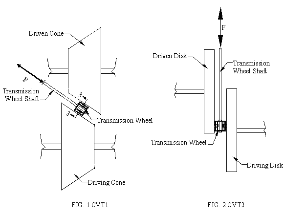
Two CVTs that can benefitfrom the transmission wheel are shown in fig. 1, where it is used to couple adriving cone with a driven cone, and in fig. 2, where it is used to couple adriving disk with a driven disk. In fig. 1 and fig. 2 the transmission ratio ofthe CVT is changed by sliding the transmission wheel in the axial direction,which is the direction shown by arrow F, relative to the surfaces of the conesor disks. In order to transmit torque, a sufficient amount of friction has toexist between the surfaces of the transmission wheel in contact with the conesor disks. In cases where the transmission wheel is replaced with a solid wheel,the surfaces of the solid wheel in contact with the surfaces of the cones ordisks have to be slid relative to the surfaces of the cones or disks. But asmentioned above by using a transmission wheel, instead of a solid wheel, thisaxial sliding can be eliminated.

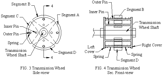
In order to eliminateaxial sliding between the torque transmitting surfaces, such a axial slidingbetween the surfaces of the cones and the transmission wheel (fig. 1) and axialsliding between the surfaces of the disk and the transmission wheel (fig. 2),the transmission wheel, as shown in fig. 3 and fig. 4, consist of four segments,segment A, segment B, segment C, and segment D, which are attached to rotatingframe as to form a continuous surface through which torque from the driving conecan be transmitted to the driven cone. During the rotation of the transmissionwheel, the segments will alternately come in and out of contact with thesurfaces of the cones. Each segment is slidably mounted on an inner pin and anouter pin. The inner and outer pins, which are securely placed between a leftcover and right cover, will maintain the wheel like shape of the transmissionwheel by restraining the rotational movements of the segments. However since thesegments can slide on the inner and outer pins, the axial positions of thesegments are independent of each other. Also, two springs are placed on eachouter pin. One spring is placed between the left cover and a segment, and theother spring is placed between the right cover and a segment. The springs willbias the segments toward the center of the frame, which comprises of the leftand right covers and the inner and outer pins. When an axial force, large enoughto overcome the resistance of the springs, is applied on a segment, then thatsegment will move in the direction of that force relative to the frame. And oncethat axial force is removed, the springs will move that segment back to thecenter of the frame.

During normal operation,where the CVT operates at its desired transmission ratio, no actuation force F,see arrow in fig. 1 and fig. 2, is applied to the transmission wheel. Therefore,during normal operation, the segments are positioned at the center of the frame.In order to change the transmission ratio, the axial position of thetransmission wheel has to be changed. In order to explain how the transmissionwheel eliminates axial sliding between the torque transmitting surfaces thatoccur when the transmission ratio is changed, we use an instantaneous situationwhere an actuation force F, see arrow in fig. 1, is applied on the transmissionwheel while segment A and segment C are out of contact with the cones (see fig.5).

Here friction between thesurfaces of the cones and segment B and segment D prevents these segments frommoving in the direction of the actuation force F. Since the segments can sliderelative to the frame of the transmission wheel, the frame of the transmissionwheel will be moved by the actuating force F, while segment B and segment D willremain at their current axial position. Since at this instances segment A andsegment C are not in contact with the surfaces of the cones, they move with theframe of the transmission wheel to the new axial position. And after thetransmission wheel has rotated 90°, segment B and segment D will be out ofcontact with the cones so that the springs, attached to the outer pins, willforce these segments back towards the center of the frame. So that after a 90°rotation, the location of the transmission wheel relative to the surface of thecones has been changed without any axial sliding between the torque transmittingsurfaces. Many variations of this idea have been worked on, such as segmentedpulleys, transmission wheels with only 2 segments, etc. If there is any interestregarding this invention or if there are engineering projects in which ourdesign experience might be helpful please use the contact information below:
| address: | CVT Research 2599 E. Temple Ave. Apt. I West Covina, CA 91792 USA |
| ph: | (626) 581 4411 |
| email: | cvtresearch@yahoo.com |
[ this site is under construction] [created: 25 Nov 2002, updated: 19 Set 2008 ] [ designed by vb.web.pt ]