CVT-
Continuously Variable Transmission
Milner CVT for High Torque
Applications
Contact InterSyn Technologies:
Michiel de Rijk
Email: michiel.derijk@intersyn.com
Website:
www.intersyn.com
Summary
Since the commencement of the Milner CVT project five years ago, development has
been concentrated on relatively low power applications (<75kW) due principally
to the wishes of the first licensee for the technology, Yamaha. During this
period the basic operating principles of the transmission were validated and, by
comparing design predictions with practical results, design methods have been
improved to the extent that there now exists a sufficiently large knowledge base
to justify moving the technology forward into the heavier duty power range
associated with automotive transmissions.
The paper discusses the constructional changes developed for heavy-duty
applications, describes the design solutions adopted, and looks at the key
performance parameters that emerge from analysis of this new version of the
Milner CVT.
Basic Operating Principles
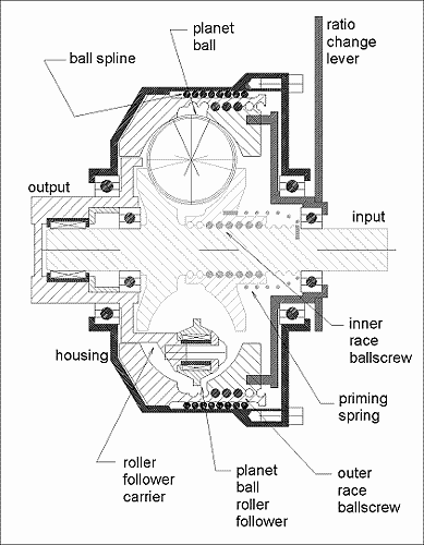
The Milner CVT (MCVT) is
a rolling traction variator of essentially simple construction. In its
original, standard form it is effectively a variable geometry four-point
contact ball bearing with the outer race held stationary, drive input to the
inner race and power take off from the bearing balls by roller followers
located between the balls and mounted on a rotating carrier; see Figure 1.
The substantial contact forces necessary to support rolling traction are
contained entirely within the races of the variator assembly. The correct
amount of contact force for any input torque is automatically generated by a
helical drive mechanism, normally a ball screw, built into the inner race
assembly. A similar type of mechanism is employed in the outer race assembly
to provide low-load ratio changing under load. How these functions are
achieved is now briefly described.
|
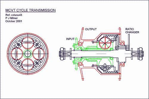
Figure 0. MCVT Cycle transmission |
Original Configuration of
Milner CVT
Tests
undertaken on a small MCVT [1] validated basic principles. In this original
form the MCVT transmits torque in one direction only and freewheels in the
other, in the manner of a sprag clutch. Due to the annular space required by
the roller followers, it is normally possible to adopt a maximum of three
planets, unless the transmission is restricted to a relatively small ratio
range. Photographs of the rolling assembly and rotating assembly (ie the
rolling assembly with the outer race set removed) of such a small ratio
range unit are shown in Figure 3, illustrating the tight packaging necessary
for the adoption of four planets.
Calculation suggests, and tests confirm [1] that the static torque capacity
of a unit such as that shown in Figure 3 can be very high. For example, a
rolling assembly of 110mm diameter can be engineered to support an input
torque of over 250Nm in the worst-case lowest ratio (and up to 750Nm in the
higher ratios) before failure. However, various factors cause real-world
torque capacity to be significantly less than this and it is consideration
these factors that has led to the development of a new form of the
transmission. |
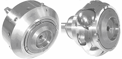
Figure 3. Example of Rolling/Rotating Assembly – Original Configuration |
|
If the torque requirement
of an application is high, but power requirement is low, then this original
configuration is normally perfectly adequate. For example, a 75mm diameter
MCVT cycle hub transmission has been designed to accept an input torque at
the wheel sprocket of 60Nm with lubrication by Santotrac traction grease.
As power (ie speed) is increased, there comes a point at which the
lubrication system must be adapted to also serve as a cooling system,
involving the use of oil instead of grease. Splash cooling is sometimes
appropriate (as for a variable speed crankshaft pulley 10kW/50Nm output
torque application with rotating, finned housing, for example) but for more
powerful applications some kind of circulatory oil cooling system is
necessary. However, in this case, only a basic, low-pressure, low power loss
circuit is required (as distinct from the high pressure, high loss circuit
required for most CVTs) and therefore adoption of a remote, electrically
powered pump is normally the preferred solution.
The inclusion of an oil cooling circuit takes the capability of the original
MCVT configuration to at least several tens of kilowatts (any upper limit is
as yet unknown) but a number of issues become increasingly difficult to deal
with effectively as design size is increased to accommodate the larger power
and ratio range requirements of automotive transmissions. These issues
include:
- Losses associated with spherical planets
- Mass implications of spherical planets
- Space occupied by roller followers
In addition, of course, automotive transmissions require full
bi-directionality of torque and rotation. In order to effectively address
all these issues a fundamental design review was undertaken that resulted in
the new heavy-duty configuration nowpresented. |
The Heavy Duty Milner CVT
Prior to illustrating an example of this new version of the MCVT, key design
changes are first described and discussed.
Planet Design
|
The design review mentioned above
identified benefits to be gained by departure from the use of solid
spherical planets for large MCVTs, fundamentally on mass grounds, and this
opened up new design opportunities that permitted the other principal
objectives also to be achieved. A large automotive transmission would
require ball planets of several kilograms mass each. Apart from the mass
penalty on the transmission as a whole, the centrifugal forces involved at
high speed also cause problems. Hollow steel and ceramic balls both offer
solutions to the mass problem, but both bring problems of their own, such as
availability and cost. Therefore, it was decided to replace the spherical
planets with items manufactured from three separate components, enabling
redundant mass to be removed. |
Having
relinquished the geometric constraints inherent in ball planets, the
opportunity was taken to shape the rolling surface of the new planet for
increased efficiency and to separate the two halves to accommodate a more
compact power take off system, resulting in the lenticular shaped, divided
planet shown in Figure 4.
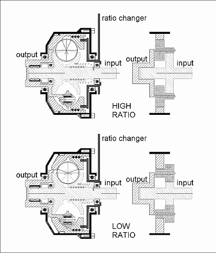
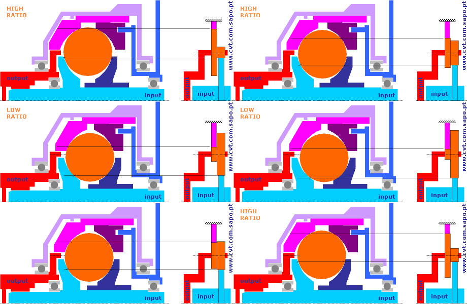
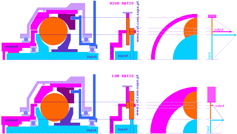
At extremes of ratio, ball planets operate under conditions of relatively
high contact zone spin. This is because these zones lie close to the axis of
planet rotation which means that the plane of the zone lies nearly
perpendicular to the rotation axis, as is clear from Figure 2 (analogous to
a ball rolling along the walls of a narrow ‘V’ shaped channel; it spins many
times before it rolls a distance equal to one diameter). This contact zone
spin, a feature of all rolling traction transmissions, is doubly detrimental
because it consumes power that both reduces efficiency and has to be removed
as heat.
In the new planet design the extreme ratio contact points still lie close to
the rotation axis (as they must do to achieve a large ratio range) but
contact zone spin is reduced by rotating the plane of the contact zone more
towards the rotation axis of the planet and away from the perpendicular to
it. This process produces the lenticular shape, as seen in Figure 4, that
operates with more of a rolling contact than a spinning one, thereby
reducing losses. |
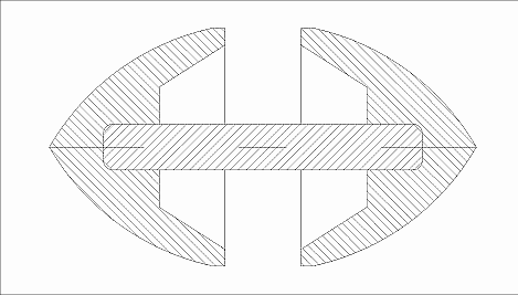
Figure 4. Planet Design for Heavy
Duty Applications |
Power Take Off System
As
mentioned previously, the change in planet concept also allowed the
incorporation of an improved power take off (PTO) system, one that in
general permits the use of one extra planet (which allows five planets to be
packaged for small ratio range applications and four planets for large ratio
range applications) thereby providing extra torque capacity for a given
transmission size. Key features of the new PTO system are illustrated in
exploded form in Figure 5.
The three-part planet is push-fit assembled after entering its central shaft
(A) into a cylindrical, needle bearing equipped sleeve(B) and
after entering the sleeve into a slotted plate (C) provided with one
slot for each planet. The slot sides are extended(D) to provide a
widened surface on which the sleeve is able to roll a small distance in a
radial direction. The plate delivers its power to the PTO hub(E) via
holes (F) in the plate that mate with fingers (G) on the hub.
|
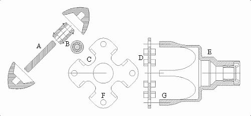
Figure 5. Power Take Off System for Heavy
Duty Applications |
Bi-Directional Drive System
The form of the transmission shown in Figure 1 is uni-directional because
only in one direction of input torque does the ball screw drive the inner
race halves together. (In the other direction the inner race halves are
driven apart, traction is lost and torque transmission drops to virtually
zero.) In order to cause both directions of torque application to drive the
inner race halves together, the heavy duty MCVT employs a single ball screw
fitted with dual ball nut inner race halves (which may be identical) as
illustrated in exploded form in Figure 6.
Inner race travel stops in the form of the collars shown either side of the
race set are fixed to the ball screw shaft. For a right hand ball screw
helix, as shown, positive torque drives the right race half to its stop and
the left race half then supplies the necessary planet clamping forces (and
vice versa for negative torque). Each collar engages its half-race via
mating pegs with an inclined interface thereby sharing the load input to the
half-race with the ball screw. The collar at the free end of the ball screw
(left in Figure 6) may be fitted with a lighter duty mounting (such as the
shear pin arrangement shown) since this collar is relatively lightly loaded,
being subject to engine braking torque only. |
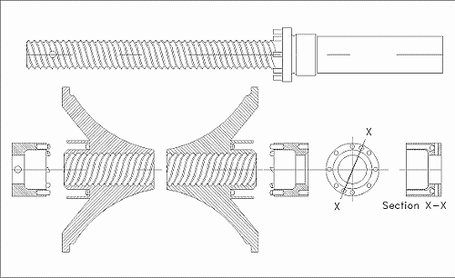
Figure 6. Inner Race Component Set for Bi-Directional Heavy Duty Application |
|
In addition to acting as travel stops,
the collars perform an important hydraulic damping function as the inner
race set runs from one stop to the other upon change of torque direction.
The damping action effectively eliminates this backlash (of typically up to
three quarters of a revolution) and also provides a hydraulic cushion at the
moment metal-to-metal drive is re-established, thereby eliminating the
possibility of noise. Oil for the damping system is supplied by the cooling
circuit, as shown in the assembly drawing, below, and is admitted to the
annular damping chambers via galleries and one-way valves indicated in
Section X-X of Figure 6. |
Heavy Duty Transmission Layout
|
Figures 7a and 7b show a
typical layout according to the new configuration. |
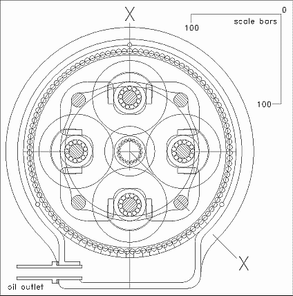
Figure 7b. Layout of Heavy Duty Milner CVT |
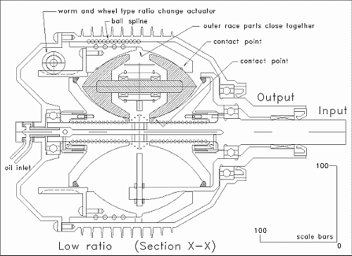
Figure 7a. Layout of Heavy Duty Milner CVT |
The unit shown, which
measures 250mm in both diameter and length, has a design input torque rating of
250Nm and an estimated cooling capacity adequate for a power rating of 150kW.
Ratings for other sizes are predicted on theoretical grounds to vary according
to linear size to the power 2.5 to 3, depending on duty cycle. Thus, for
example, a unit of 300mm diameter and length would have a design input torque
rating of between 394Nm (=250x(300/250)^2.5) and 432Nm (=250x(300/250)^3). The
above ratings are very conservative (static factor-of-safety = 3, fatigue life =
10Grev) and calculation suggests that they could be as much as twice the quoted
figures, given adequate cooling.
A worm and wheel type ratio change actuator is illustrated but other types are
also suitable. Total travel of the wheel between ratio extremes is about half a
revolution, making rapid ratio changes possible, if required, even under load.
For example, a 1Nm/3000rpm motor will shift the entire ratio range in one
second, even under full load. An advantage of the worm and wheel drive is that
no holding current is required to maintain ratio even under full load
conditions.
The Figure 7 drawings show the unit in
its lowest ratio, which is a reduction of 9.0:1, while Figure 8 shows it in
its highest rolling ratio, which is a reduction of 1.28:1, for a ratio range
of 7.0, and Figure 9 shows it in an optional lock-up-top condition (which is
1:1, for a ratio range of 9.0, of course). Note that the shift to lock-up is
a step shift.
In all conditions except the lowest ratio, the inner race halves are closer
together than when in lowest ratio. In these conditions the entire rolling
assembly takes up an axial position as determined by the right collar stop
under positive drive torque, as shown in Figures 8 and 9, and by the left
collar stop under negative drive torque (engine braking).
The maximum coefficient of traction demanded by the design described here is
0.06, which has proved to be satisfactory for earlier MCVT designs when
using Santotrac 50 traction fluid for lubrication and cooling. It will be
appreciated that the coefficient of traction demanded may be altered simply
by changing the helix angle of the inner race ball screw.
As shown in the figures, input and output shafts lie on the same side of the
transmission, but for applications where it is advantageous for them to lie
on opposite sides this is readily accomplished with only the oil inlet
arrangements requiring significant alteration.
With steel as the material for the planets and races, efficiency is
predicted to be 90% or greater in all ratios (apart from the optional
super-efficient lock-up top condition) but it is known from tests with an
earlier MCVT design [1] that silicon nitride components produce an
efficiency boost of several percent. It should also be noted that in the
MCVT most of the losses occur at the rolling interfaces, with very little
power lost elsewhere. This means that efficiency under part- and low-load
conditions is much the same as under full load, unlike most other CVTs that
are burdened, particularly under lighter load conditions, by the substantial
‘parasitic’ losses of a high-pressure hydraulic control system. |
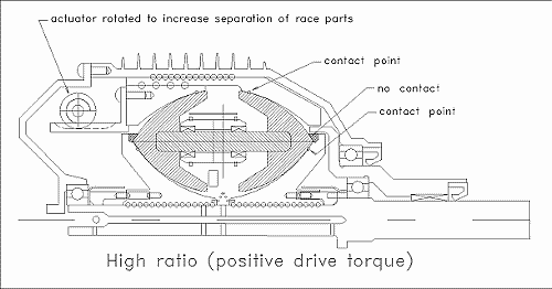
Figure 8. Highest Rolling Ratio |
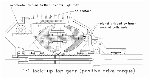
Figure 9. Lock-Up Top Gear |
Conclusions
The modifications described make the Milner CVT concept suitable for high
torque, high power automotive driveline applications. In this form the Milner
CVT offers all the features required of manual, semi-automatic and automatic
transmissions in a single package.
References
[1] ‘Performance Investigations of a Novel Rolling Traction CVT’, Akehurst S, et
al, SAE Technical Paper 2001-01-0874
For more information contact:
InterSyn Technologies: Michiel de Rijk
Email: michiel.derijk@intersyn.com
Website:
www.intersyn.com
[ this site is under
construction] [created: 14 Nov 2002, updated:
19 Set 2008
] [ designed by vb.web.pt ]

